PRACTICAL CIRCUITS
What is the function of a power supply bleeder resistor?
-
It acts as a fuse for excess voltage
-
Correct AnswerIt discharges the filter capacitors when power is removed
-
It removes shock hazards from the induction coils
-
It eliminates ground loop current
Hint: a Bleeder causes a Discharge blood
The bleeder resister of a power supply performs the safety feature of discharging the filter capacitors. The resistor is arranged in parallel with the power supply. The use of the resistor is very important in this application, as it lowers the risk of electric shock from stored electrical energy in the filter capacitors by allowing the voltage level to decay quickly when the power supply is shut off.
For more info see Wikipedia: Bleeder resistor
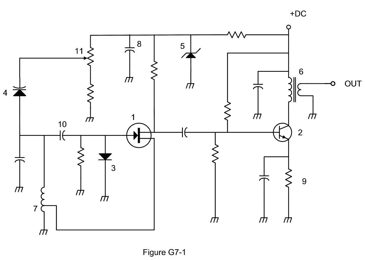
The bleeder resistor is shown as symbol 9 on the G7-1 schematic for the general class exam.
Link to circuit symbol guide: [Wikipedia Gallery of Common Electronic Symbols] (http://en.wikipedia.org/wiki/Electronic_symbol#Gallery_of_common_electronic_s ymbols)
Hint: The question and answer both have power.
Last edited by donaldbush. Register to edit

Which symbol in figure G7-1 represents a field effect transistor?
-
Symbol 2
-
Symbol 5
-
Correct AnswerSymbol 1
-
Symbol 4
Symbol 1 in figure G7-1 represents a field effect transistor.
The figure shows the arrow coming IN from the GATE to meet the vertical bar, representing the transistor, at center left. At the top of the bar the upper terminal has a perpendicular line to the right indicating the DRAIN. While at the bottom of the bar the lower terminal has a perpendicular line to the right indicating the SOURCE.
Link to circuit symbol guide: Wikipedia Gallery of Common Electronic Symbols
For more info see Wikipedia: Field effect transistor
Last edited by kd7bbc. Register to edit
Which symbol in figure G7-1 represents a Zener diode?
-
Symbol 4
-
Symbol 1
-
Symbol 11
-
Correct AnswerSymbol 5
(D). Symbol 5 represents a Zener diode.
The figure is represented by a horizonal bar across the vertical circuit line. The left end of this bar tilts down, and the right end tilts up. These tilts represent the change in voltage beween the input and output. These tilts make it look a little like a Z on its side - as a reminder for "Zener." Pointing into the bottom center of the horizontal bar is a triangle, located on the circuit line and the tip hitting the bar. This triangle symbol represents the voltage drop, D, of the diode.
Note for the visually impaired: If possible, notify your VE in advance of any accommodation you may need. They may be able to give you an exam without questions on figure G7-1. A worded description of the symbol is given here for both your own knowledge and to be able to describe the symbol to the VE if necessary.
Refer to the following links for the official exam circuit figure and symbol guide:
Figure G7-1 (.jpg format): http://www.ncvec.org/downloads/Revised%20G7-1.jpg
Figure G7-1 (.pdf format): http://www.ncvec.org/downloads/Revised%20G7-1.pdf
Link to circuit symbol guide: Wikipedia Gallery of Common Electronic Symbols
For more info see Wikipedia: Zener diode
Last edited by qubit. Register to edit
Which symbol in figure G7-1 represents an NPN junction transistor?
-
Symbol 1
-
Correct AnswerSymbol 2
-
Symbol 7
-
Symbol 11
Symbol 2 represents an NPN junction transistor. A common way to remember the symbol for an NPN transistor is that the arrow is Not Pointing iN.
The transistor is represented by a vertical bar with a line coming in to the center of the bar from the left (Base). The upper terminal has a line coming into the right at an upward 45 degree angle (Collector). The lower terminal has a line to the right downward 45 degree angle (Emitter) with an arrow pointing away from the transistor.
Note for the visually impaired:
If possible, notify your VE in advance of any accommodation you may need. They may be able to give you an exam without questions on figure G7-1. A worded description of the symbol is given here for both your own knowledge and to be able to describe the symbol to the VE if necessary.
Refer to the following links for the official exam circuit figure and symbol guide:
Link to circuit symbol guide: Wikipedia Gallery of Common Electronic Symbols
For more info see Wikipedia: NPN or Bipolar junction transistor
Last edited by kd7bbc. Register to edit
Which symbol in Figure G7-1 represents a solid core transformer?
-
Symbol 4
-
Symbol 7
-
Correct AnswerSymbol 6
-
Symbol 1
(C). Symbol 6 represents a multiple-winding transformer.
The core of the transformer is represented by two long vertical parallel lines close together (if there were no lines, the core would be air). On the left side of the core is the primary winding represented as vertical line with multiple connected semi-circular dips or waves, with the bottoms of the waves towards the core, and the pointed wave peaks pointing away from the core. On the right side is the secondary winding represented by a similar wavy line (bottoms of the waves toward the core). The number of windings on the two sides can be the same or different (which would indicate a step-up or step-down transformer). The symbol shown in figure G7-1 shows 4 windings on the left and 2 on the right.)
Refer to the following links for the official exam circuit figure and symbol guide:
Figure G7-1 (.jpg format) (result: 404 Error Message)
Figure G7-1 (.pdf format) (result: 404 Error Message)
Link to circuit symbol guide: Wikipedia Gallery of Common Electronic Symbols
For more info see Wikipedia: Multiple-winding transformer
Last edited by zayaan.raeid. Register to edit
Which symbol in Figure G7-1 represents a tapped inductor?
-
Correct AnswerSymbol 7
-
Symbol 11
-
Symbol 6
-
Symbol 1
An inductor is a coil; symbol 7 is mostly the same symbol as a normal inductor, which is intended to represent that coil. (note symbol 6 as well which is a transformer, which consists of two coils).
A tapped inductor is one in which it's possible to "tap" a point in the coil to effectively shorten the coil. Sometimes that tap can be moved. Thus the symbol shows a wire coming off of the side of the coil in the symbol, indicating the tap.
Last edited by ironcal67. Register to edit